Loudspeakers
| Name | Serial No. | AAU No. |
|---|---|---|
| Brüel & Kjær OmniPower 4296 | 2251009 | 33950 |
| Brüel & Kjær OmniSource 4295 | 2705455 | 86831 |
| Custom-made 3'' directional loudspeaker | 47 | N/A |
You can download an estimate of the on-axis impulse response of the 3'' directional loudspeaker. Note that the impulse response has has been measured in a 2pi/infinite baffle and has neither been time-aligned nor high-pass filtered. The impulse response is measured by Martin Olsen from Bang & Olufsen A/S.
Microphones
Up to 23 microphones are used. These microphones and microphone pre-amplifiers are all of the type
- G.R.A.S. Prepolarized Free Field Microphone 40AZ and
- G.R.A.S. 26CC Microphone pre-amplifier, respectively.
Instead of a microphone, one of the microphones pre-amplifiers is mounted with a dummy microphone of the type
- Bruel & Kjaer JJ-2617 Coaxial input adapter (51 pF).
In the table below, the mappings between the microphones, the microphone pre-amplifiers, and the ADC input channels are listed. The connection column denotes the electrical connection between the microphones (which are in the listening room) and the ADCs (which are in the control room). The ADC channel notation X.Y should be read as ADC X ch. Y. Finally, the label in the parenthesis after the ADC channel refers to the microphone name. For example, O1X refers to the first microphone in the x-direction of the orthogonal array whereas ULA 5B refers to the fifth microphone on the second uniform linear array. The label 'loop back' refers to the loop back connection from the loudspeaker input channel to an ADC input channel.
| Connection | Mic. Serial No. | Pre-amp. Serial No. |
ADC ch. Conf. XX0X |
ADC Ch. conf. XX1X | ADC Ch. conf. XX2X |
|---|---|---|---|---|---|
| 1A | 100230 | 78045 | 1.1 (O1X) | 1.7 (ULA 1A) | 1.1 (UCA 1A) |
| 2A | 100231 | 78170 | 1.2 (O2X) | 1.6 (ULA 2A) | 1.2 (UCA 2A) |
| 3A | 100248 | 78165 | 1.3 (O3X) | 1.5 (ULA 3A) | 1.3 (UCA 3A) |
| 4A | 100243 | 78168 | 1.4 (O4X) | 1.4 (ULA 4A) | 1.4 (UCA 4A) |
| 5A | 100244 | 78164 | 1.5 (O5X) | 1.3 (ULA 5A) | 1.5 (UCA 5A) |
| 6A | 100242 | 78049 | 1.6 (O6X) | 1.2 (ULA 6A) | 1.6 (UCA 6A) |
| 7A | 100236 | 78031 | 1.7 (O7X) | 1.1 (ULA 7A) | N/A |
| 8A | 100246 | 78136 | 2.1 (O1Y) | 2.1 (ULA 1B) | 2.1 (UCA 1B) |
| 9A | 100240 | 78029 | 2.2 (O2Y) | 2.2 (ULA 2B) | 2.2 (UCA 2B) |
| 10A | 100229 | 78177 | 2.3 (O3Y) | 2.3 (ULA 3B) | 2.3 (UCA 3B) |
| 11A | 100232 | 78180 | 2.4 (O4Y) | 2.4 (ULA 4B) | 2.4 (UCA 4B) |
| 12A | 100233 | 78181 | 2.5 (O5Y) | 2.5 (ULA 5B) | 2.5 (UCA 5B) |
| 1B | 100261 | 78041 | 3.1 (O1Z) | 2.6 (ULA 6B) | 2.6 (UCA 6B) |
| 2B | 100265 | 78161 | 3.2 (O2Z) | 2.7 (ULA 7B) | N/A |
| 3B | 100235 | 78163 | 3.3 (O3Z) | 3.7 (ULA 1C) | 3.7 (ULA 1C) |
| 4B | 100245 | 78171 | 3.4 (O4Z) | 3.6 (ULA 2C) | 3.6 (ULA 2C) |
| 5B | 100247 | 78169 | 3.5 (O5Z) | 3.5 (ULA 3C) | 3.5 (ULA 3C) |
| 6B | 100259 | 78162 | 3.6 (O6Z) | 3.4 (ULA 4C) | 3.4 (ULA 4C) |
| 7B | 100260 | 78174 | 3.7 (O7Z) | 3.3 (ULA 5C) | 3.3 (ULA 5C) |
| 8B | 100266 | 78186 | 2.6 (O6Y) | 3.2 (ULA 6C) | 3.2 (ULA 6C) |
| 9B | 100263 | 78172 | 2.7 (O7Y) | 3.1 (ULA 7C) | 3.1 (ULA 7C) |
| 10B | N/A | 78167 | 2.8 (Dummy) | 2.8 (Dummy) | 2.8 (Dummy) |
| 11B | 100252 | 78183 | 3.8 (Single) | N/A | N/A |
| N/A | N/A | N/A | 1.8 (Loop back) | 1.8 (Loop back) | 1.8 (Loop back) |
Microphone Arrays
Four microphone arrays were used in the recordings.
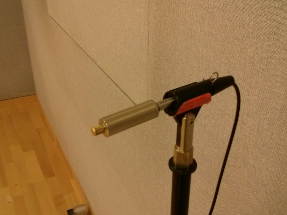
- The simplest array was just a single microphone (Fig. 7).
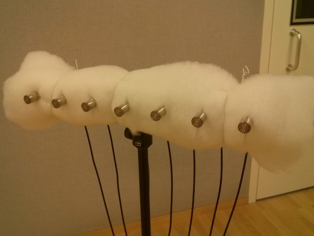
- Three uniform linear arrays (ULA) were used (Fig. 5). Each ULA consisted of seven microphones which were separated by 5 cm. The microphones were indexed from 1 to 7 with the microphone farthest to the right (when viewed from the front) having index number one.
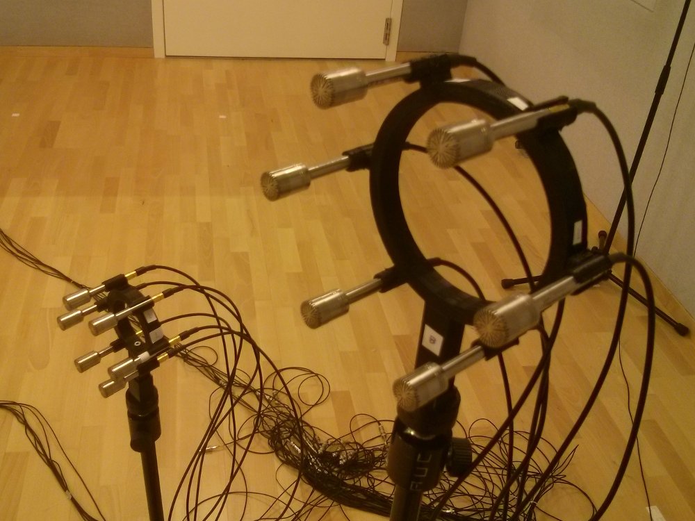
- Two uniform circular arrays (UCA) were used (Fig 6). The radii of these two UCAs were 4 cm and 6 cm, respectively. The microphones were indexed from one to six in the the counter-clock wise direction with the microphone at the three o'clock position (when viewed from the front) having index number one.
- An orthogonal array consisting of the three ULAs pointing in the x-, y-, and z-direction (Fig. 4).
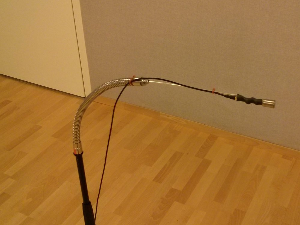
Besides these microphone array, a dummy microphone was used (Fig. 8).
In the table below, it is depicted how the columns of the data matrix (.dataMatrix) of the struct returned by the loadSmarData.m function are mapped to different microphone and loop back signals:
|
Column no. |
Mic. in conf. XX0X |
Mic. in conf. XX1X | Mic. in conf. XX2X |
|---|---|---|---|
| 1 | O1X | ULA 1A | UCA 1A |
| 2 | O2X | ULA 2A | UCA 2A |
| 3 | O3X | ULA 3A | UCA 3A |
| 4 | O4X | ULA 4A | UCA 4A |
| 5 | O5X | ULA 5A | UCA 5A |
| 6 | O6X | ULA 6A | UCA 6A |
| 7 | O7X | ULA 7A | N/A |
| 8 | Loop back | Loop back | Loop back) |
| 9 | O1Y | ULA 1B | UCA 1B |
| 10 | O2Y | ULA 2B | UCA 2B |
| 11 | O3Y | ULA 3B | UCA 3B |
| 12 | O4Y | ULA 4B | UCA 4B |
| 13 | O5Y | ULA 5B | UCA 5B |
| 14 | O6Y | ULA 6B | UCA 6B |
| 15 | O7Y | ULA 7B | N/A |
| 16 | Dummy | Dummy | Dummy |
| 17 | O1Z | ULA 1C | ULA 1C |
| 18 | O2Z | ULA 2C | ULA 2C |
| 19 | O3Z | ULA 3C | ULA 3C |
| 20 | O4Z | ULA 4C | ULA 4C |
| 21 | O5Z | ULA 5C | ULA 5C |
| 22 | O6Z | ULA 6C | ULA 6C |
| 23 | O7Z | ULA 7C | ULA 7C |
| 24 | Single | N/A | N/A |
A/D Converters
The three A/D converters (ADC) used were all of the type
The first ADC in the table above has the AAU no. 56543, the second ADC has the AAU no. 56545, and the third ADC has the AAU no. 61403. The three ADC units were all isolated electrically via the B&O Power Supply RT12 with AAU number 08691.
D/A Converters
Besides four dual-channel ADCs, the Behringer Ultragain Pro-8 Digital ADA8000 also contain eight dual channel D/A converters (DAC). From the unit with AAU no. 56543, the first DAC channel was connected to the power amplifier whereas the second channel was connected to ADC channel 8 (the loop back signal in the tabel above).
Power Amplifier
Rotel RB-976 with AAU no. 33973. After a loudspeaker had been changed in the configuration setup, the volume was adjusted so that the sound pressure level (SPL) was approximately 80 dBA 1 m from the loudspeaker (on axis). The measured SPL is stored in the configuration files in the database and was measured using a Brüel & Kjær 2238 Mediator.
Sound Card
The sound card was of the type RME Digi 9652 Project Hammerfall with expansion board (no AAU no.) and connected to the ADCs via the optical ADAT interface. The sampling frequency of ADCs were controlled via the sound card's word clock.
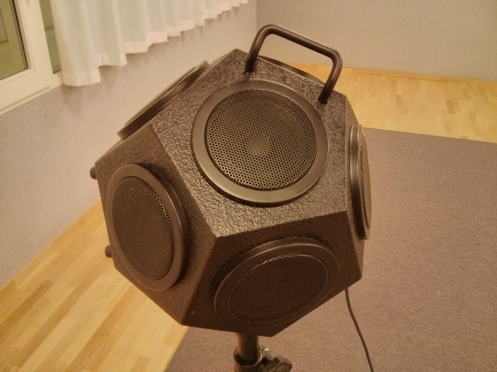 Fig 1. The B&K Omnisource 4296
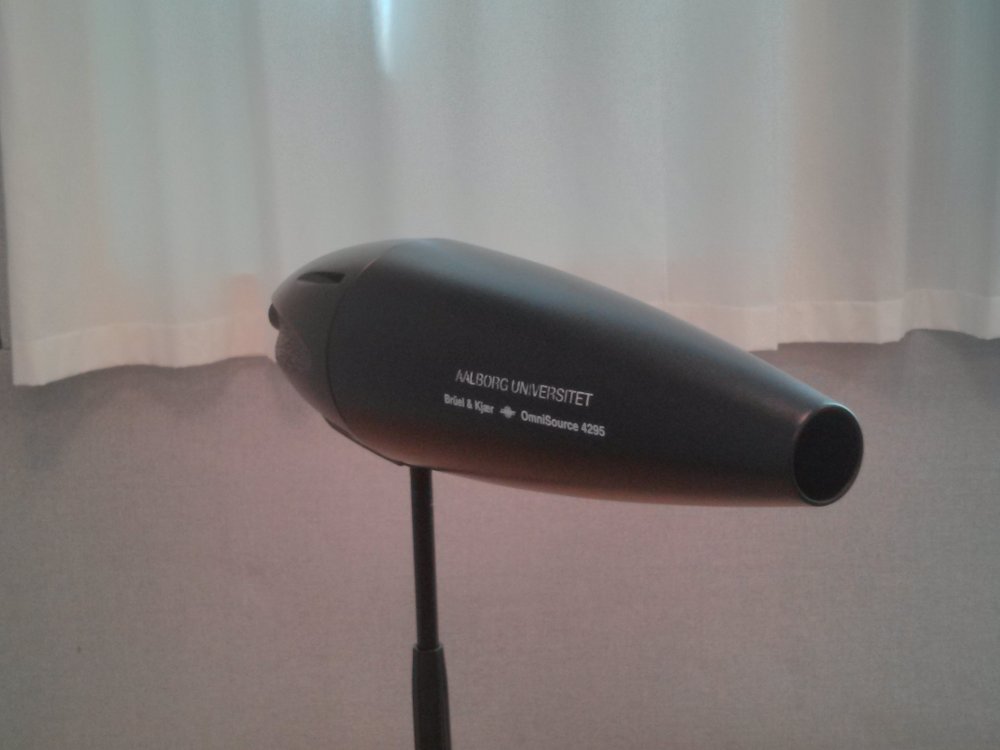 Fig. 2. The B&K OmniSource 4295
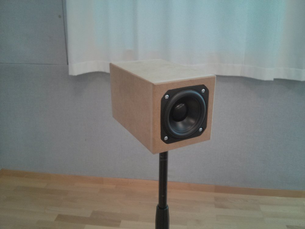 Fig. 3. The 3'' directional loudspeaker
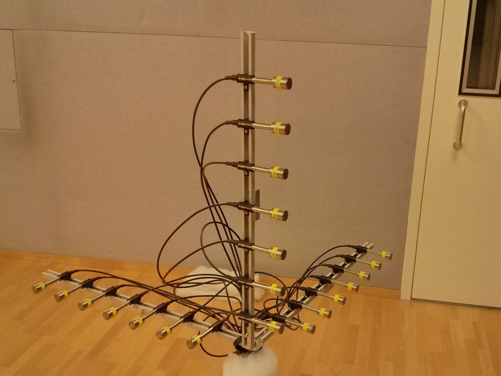 Fig. 4. The orthogonal array without foam. The measurements were made with foam (see the ULA in fig. 5)